Does anyone have a modified antenna array template that will cover the 2m ham radio band?
Thanks!!
Does anyone have a modified antenna array template that will cover the 2m ham radio band?
Thanks!!
For the 2m band the array will be quite large, not something easily printed on a paper or 3D printed.
Best to use the Excel calculator https://github.com/krakenrf/krakensdr_docs/raw/main/antenna_array/Antenna_Array_Size_Calculator.xlsx. Enter the frequency, choose the largest feasible antenna Max radius, and then use the “Antenna Coordinates for Radius” calculator to get the coordinates of each element.
I punched in the full size 88cm into the antenna array calculator for 145mhz. Is it normal for it to generate an asymmetrical configuration? Just want to make sure before I CNC a custom jig out of a sheet of 1/4" plywood.
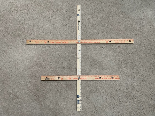
Here’s a tool I made from yardsticks for kraken antenna setup. I use .28m to (barely) cover 2m & 70cm. The trick (it’s been 50 years since my last trig class  ) was to make the drilled holes relative to the upper bolt, not the center, so only the lower bar has to be moved if you want different spacing. Just an idea…
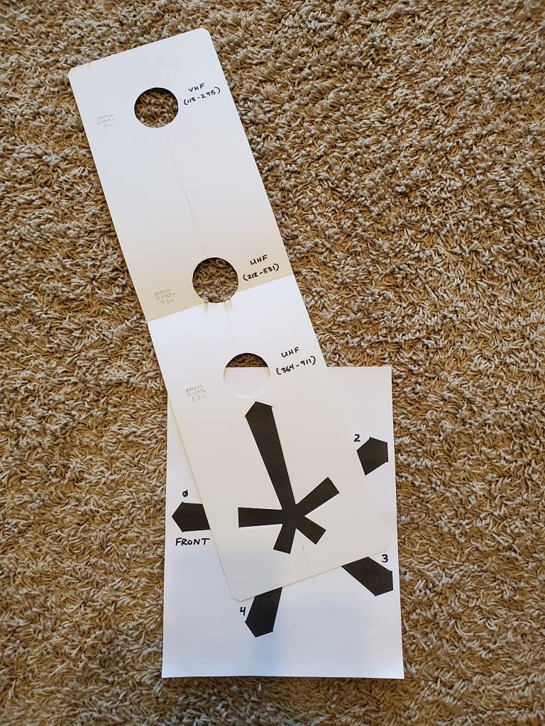
Here is the template I created for the bands I’m interested in, which includes the 2m and 70cm ham bands and much of the 70cm business and public service bands. Using the spreadsheet, these are the three general ranges I settled on:
VHF (118-295 Mhz). Radius is a big 17 inches (0.4318m).
UHF (212-531 Mhz). Radius is 9.5 inches (0.2413m).
UHF (364-911 Mhz). Radius is 5.5 inches (0.1397m).
I bought a poster board from an office supply store and cut out a 22x6 inch section and layed out a center line with these radius lengths. I then printed out 2 copies of the base template, full size on 8.5x11 inch paper. One to keep for use on the vehicle and one for cutting out, using an exacto blade, the base template and antenna base outlines on the poster board as shown. This poster board folds up to store with the base template and works out very quickly to set up the antenna array.
The shape of the antenna array will always be a pentagram with 5-elements, so asymmetrical on one axis.
I’ve been seeing a bunch of reports from people using the array calculator that claim the array is not symmetrical as expected. I think what you’ll find is that it is not DISPLAYED symmetrically, because the axes of the plot aren’t at the same scale. However if you do the math on the coordinates, it should be A-Ok.
hi sir. i want to df for 433 MHz can any one guide me
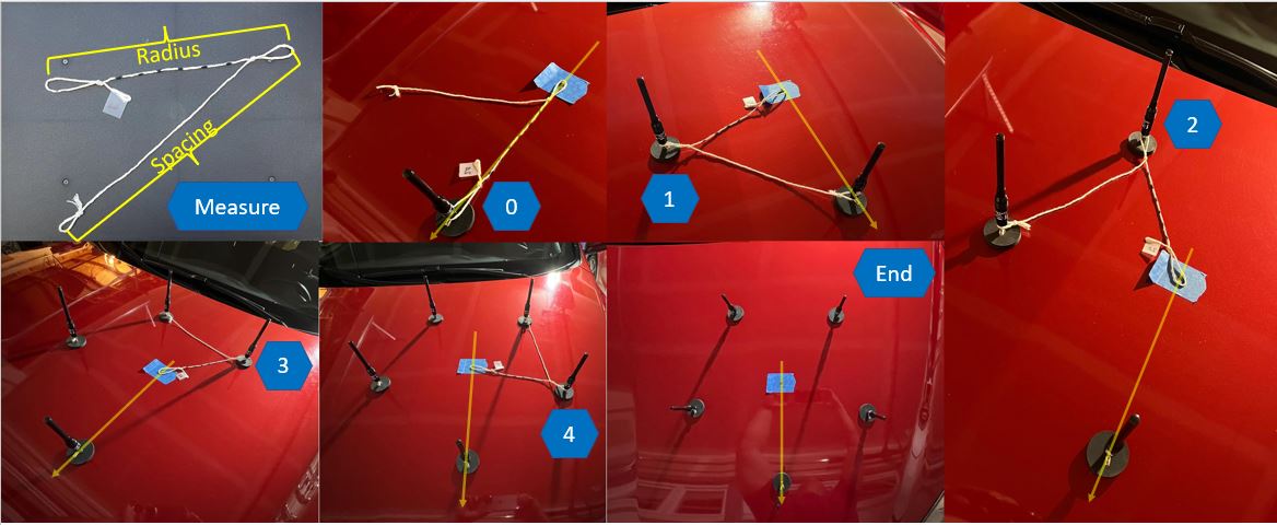
For my array, I used a string with a three loops in it, one at each end and one near the middle.
The distance between the end loops is the array radius + the inter-element spacing from the spreadsheet.
The distance form one end loop to the loop in the middle is the radius. That end is the radius loop. The distance from the middle loop to the other end loop is the inter-element spacing from the spreadsheet. That end is the spacing loop.
To use:
It’s harder to describe than it is to actually do.
After the first time, you can set up an array very quickly.
I have strings for 25cm, 45cm, and 60cm radii.
The printed templates are nice, but for people with only wire and string at their disposal, this is another option.
Would you mind posting a picture, please?
The picture shows the loops reversed from the previous instructions, but for that measure, it doesn’t matter. The rest of the steps should match the photos. The yellow line represents the center line and points to the front to show the orientation of antenna 0 as the angle of the photos is different in each shot.
In practice, pulling on the ends in a triangle shortens the distance between the ends and the middle loop slightly. It doesn’t seem to bother the results too much, but if you want to be precise, you could place the elements where they belong and use a slip-knot to calibrate the distance between loops under tension, or use something like a ring or a washer for the middle loop.
The end picture looks like they’re a little uneven, but that’s because I couldn’t put tension on the string and take a picture of it at the same time. Also, I did this on the car’s hood, which is slightly curved. As such, the geometry is slightly off. It all works out on a flat surface.
whats Holding me back From Purchasing one f these units is the antenna templates. As a broadcast Engineer trying to track down Pirates. and Being a Ham. looking for Jammers. I need a broadband antenna system. where I do not really have to stop and change the spacings drastically.
and to go as low as 88.1Mhz. Currently using an adrino based RDF with 4 antennas. with a VHF and UHF setup. A switcher system in a box for 10 antennas or 15 antennas Both UHF/VHF with the 5 outputs to the main Processor would make things easier into the Box in my case 1 set for 2 meters 1 set for 220Mhz and 1 set For Uhf or will all the antennas interfere with each Other… I dont have that issue with 8 antennas currently Just asking
According the Arrow DF antenna docs, having multiple antennas inside the array can mess up the DF performance. The circular array diameter for the higher frequencies can be pretty small. Depending on how big your mounting area is, you might be able to fit one in front/along side the other.
From looking at the Array calculator, the linear arrays seem to work over a wider freq. range, so they might be an option. The directional ambiguity of the linear array can be sorted out pretty quickly by moving and seeing on which side the angles converge.
Playing with the array calculator, a single linear array of 100cm length overall covers 109 - 545 MHz - the 144, 220, 440 ham bands. I haven’t tried this (yet), but it looks promising on paper.
That is true, but the performance of linear arrays can be a bit misleading. Think about what a linear array looks like from the side angles. As you look at it from an angle, the 2D projection of the linear array becomes smaller and smaller. So a linear array is only really working well from a small range of angles orthogonal to the array where the array looks wide. Signals arriving near the edge angles will give poor results.
Slightly off topic, but I would be interested in hearing about your Arduino based RDF unit.
New install here.
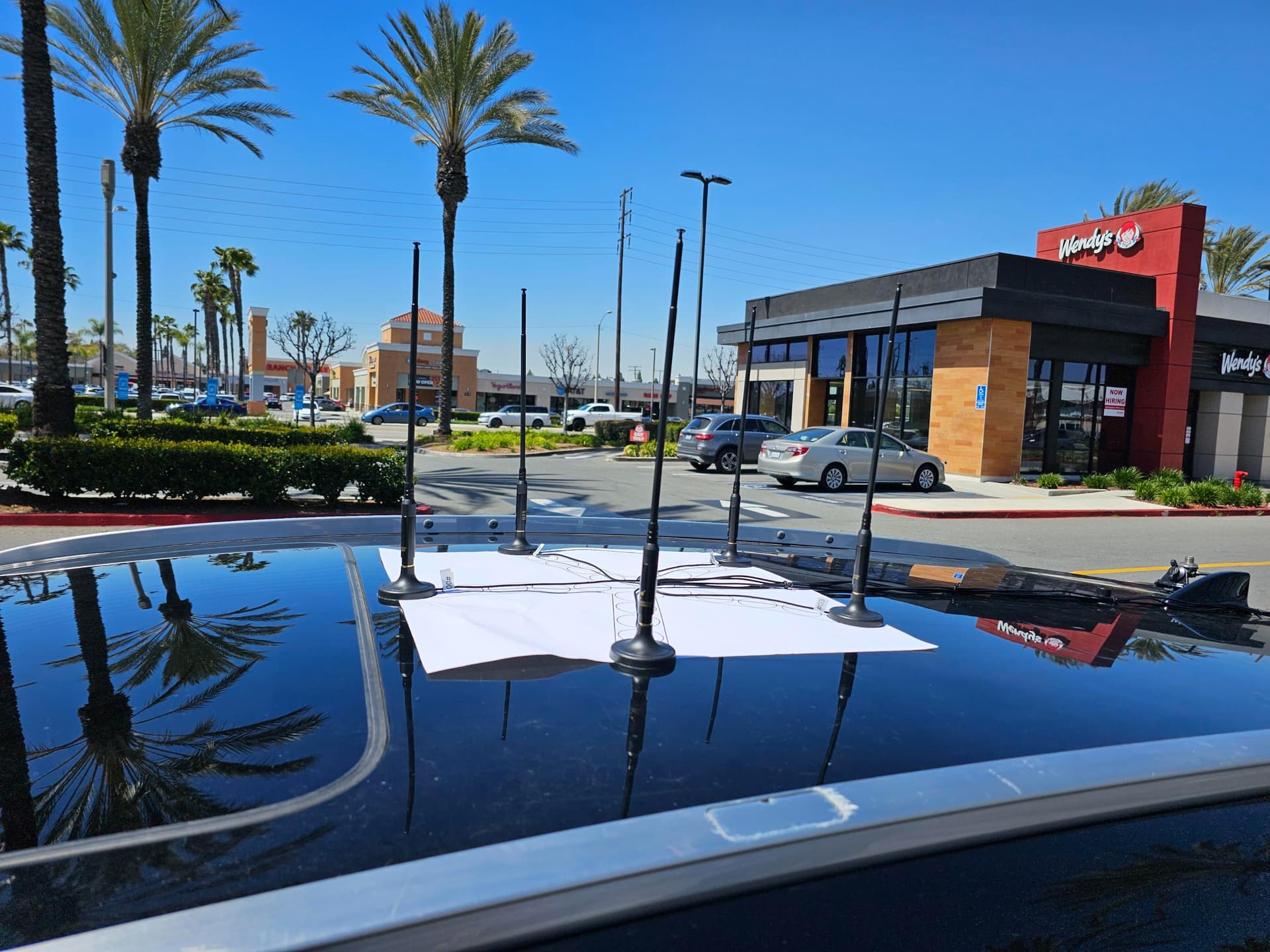
I got my Kraken device a week ago, but the Kraken antenna sets are still on back-order, so I picked up some cheapo Amazon mag-mounts and telescoping antennas for testing. They had 3m long cables that were exactly the same length fortunately. I chose to run the cables back toward the rear hatch as it has plenty of clearance for cables without pinching them.
Before starting, I went to a place with a large printer and used the “full array” template rather than trying to glue the separate center and leg parts together. It wound up on a 22" x 22" piece of paper.
I did have to tape down the template to the roof to keep it from coming up from wind while moving.
I am primarily after UHF signals in the 420-450mhz range, so I set the radius of each one to 26.1cm with the proper interelement spacing. This gives me up to 488mhz with approximately a .450 wavelength multiplier at 440mhz.
The results have been phenomenal to say the least. The only problem was the mag mounts I got were kind of cheap and moved around a bit… so I had to keep putting them back where they should be.
At one point last week, one of them blew off and took the other 4 with it. No damage, but we had to come up with something better.
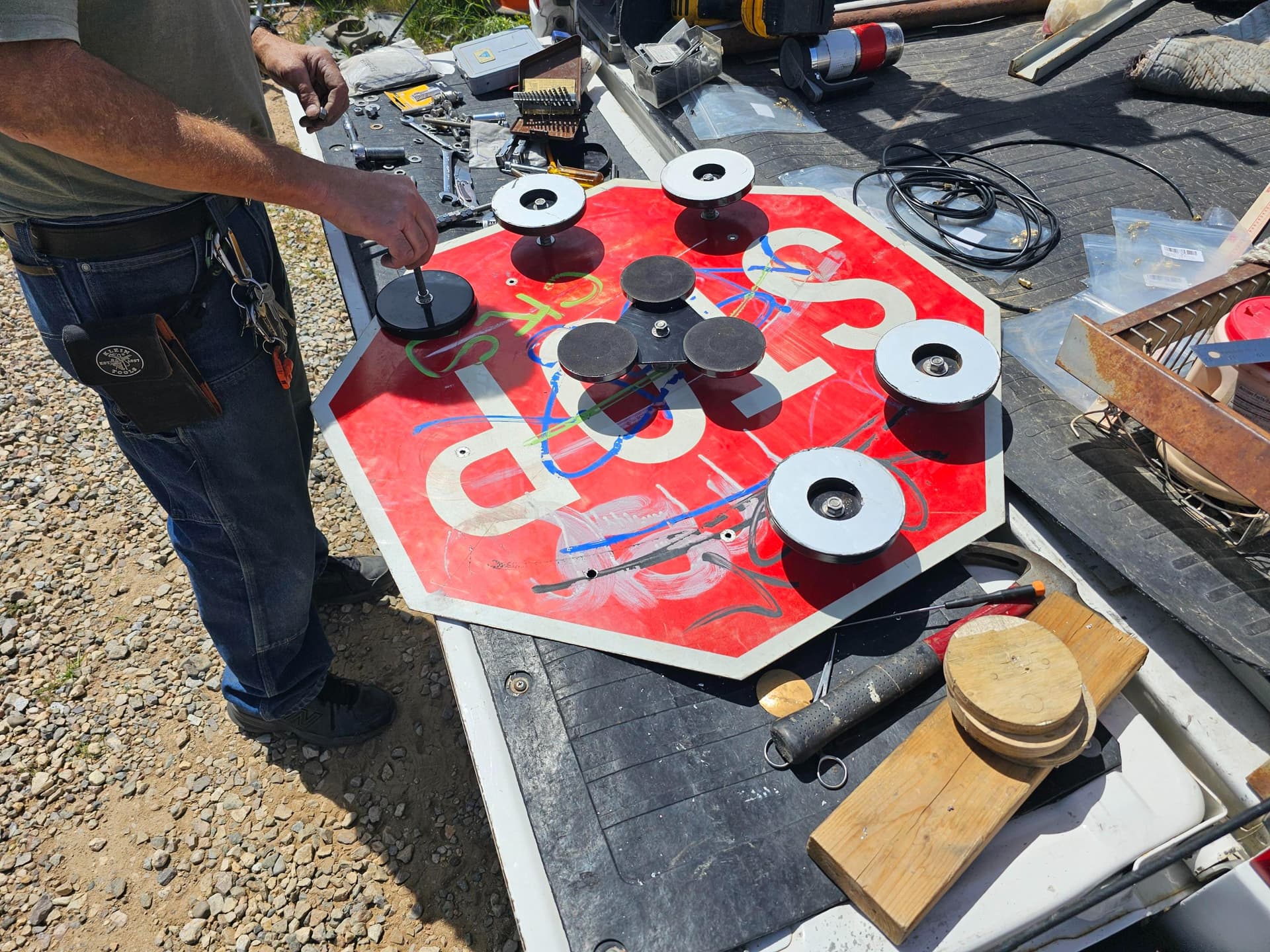
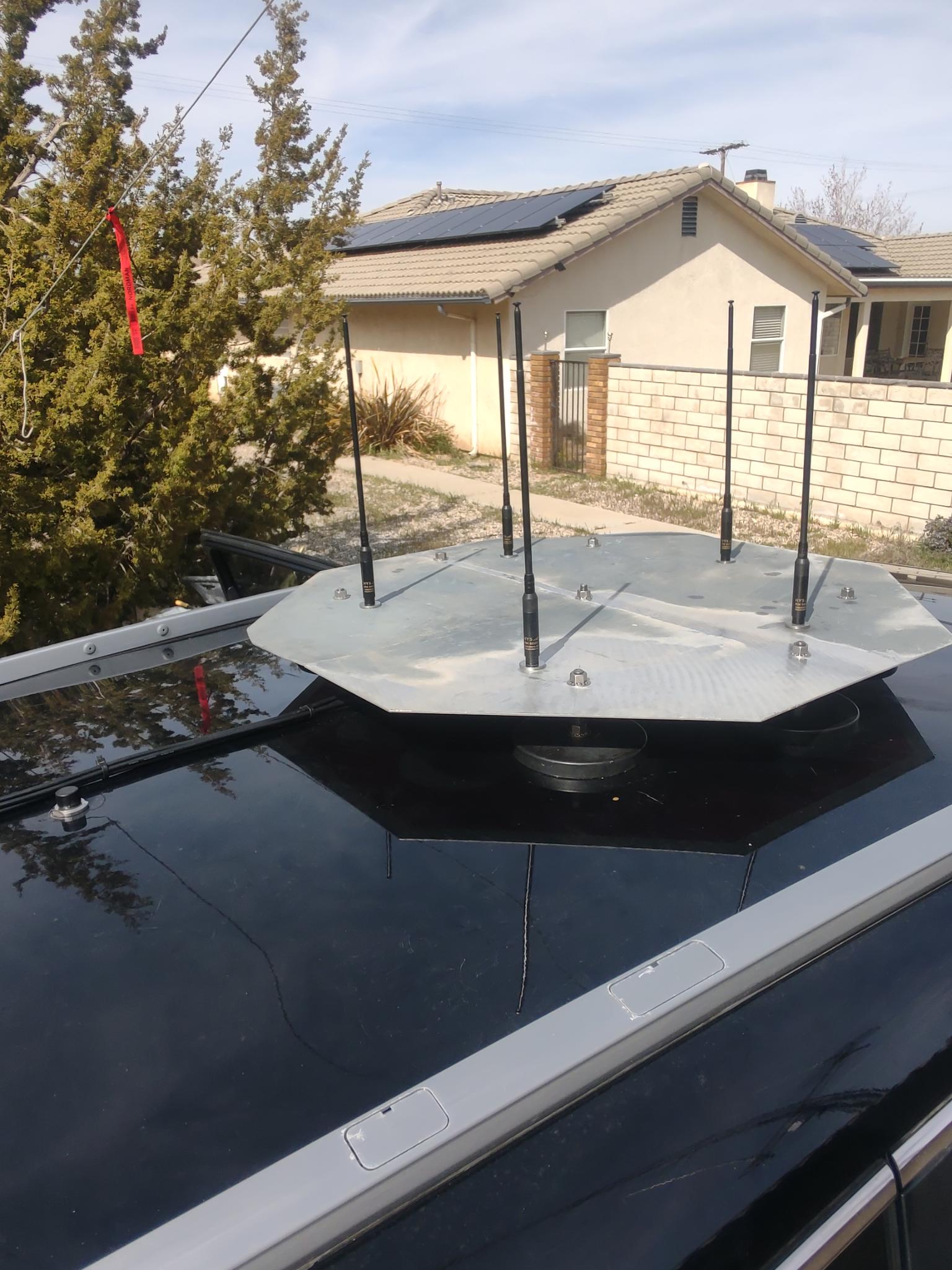
So, this past weekend, we decided to make use of a old graffiti-covered “STOP” sign that had been tossed. It is 30" across… so that left room around the outside for mounting purposes and still fit the
array for UHF in the middle.
We precision drilled it for the 5 antennas with exact spacing (within 1mm) and used new 3-meter long identical-length cables (SMA male to female bulk-head) on it. We then attached 6 large “super” magnets to the plate as well as a 3-magnet super magnet in the very center. All of the magnets are on the bottom side. The magnets are all adjustable height to help even out the “turtle” shaped roof on my car.
We got it on the car and it won’t budge without considerable effort, so it’s nice and secure. We ran the cables evenly (brought them all together in the center underneath the plate (stop sign) and tied them all together all the way back into the car via the rear hatch.
Note: We used some large washers that go over the outside of the SMA bulkhead nuts for added stability to the antennas themselves and for some strain relief on those. A better idea for this is coming.
Results: It works even better now. Even at very high freeway speeds, the whole thing stayed in place. No movement at all. My only concern is “low bridges” or parking garages. I have to take the antennas off in those situations… or snap.
I just wanted to share what it looked like with the mag mounts and then the “stop” sign mount.
Cheers!
Good morning
I have the same problem with the roof of the turtle-shaped car.
Can you tell me where you found the 6 “big super magnets”?
The Stop sign is surely in Aluminium?.
Congrats on your edit
The magnets came from 2 of the the “TRAM 269 Triple 5” Magnet CB Antenna Mount" mounts.
Each one has 3 large magnets on it that are usually attached to a small plate. We took the plate off and separated the magnets. This gave us 6 large magnets to work with.
The center one is a smaller version but we left all 3 magnets on it.
The plate (stop sign) is aluminum, about 1/16" thick.
I was going to have a piece of metal made, but we used the “STOP” sign because it was just laying around in the scrap-heap, but you can actually buy a brand-new metal 30" “STOP” sign from Amazon for about $80.
My Kraken antenna set will be here today, so I may use the antennas from it on this same mount instead of the ones I have now, and keep the Kraken mag-mounts for VHF or testing.
The antennas I’m using now… I’ve had a few that were kind of at an angle from the factory, so I had to get a few more to get ones that were perfectly straight. They are telescoping like the ones from Kraken but obviously lower quality.
One more thing: I did use a VNA on all the cables to make sure they all were matched (including length) so I didn’t run into any problems with phasing, etc.
Hope this helps.
Thank you so much.
I will think about all this
Thats impressive, good job! ![]()