The lowest risk Kraken DOA bundle for special relativity experiment?

I’m putting together an experiment to test special relativity.
The BOM for the instrument must qualitatively detect phase change between two antennas.

The requirements:

  • 2 antennas*.
  • The Kraken DOA software GUI’s DOA graph changes in response to a change in the phase relationship between the 2 antennas.
  • Tuned frequency in the 88.0MHz to 108.0MHz range**.
  • Set up be simple enough that a typical secondary school physics teacher can assemble and test the DOA system, as such, with about 8 hours investment.

After a good deal of playing with the software and RTL-SDR v3 hardware related to this (not the Kraken DOA hardware itself), I’ve determined that in all likelihood the best way to achieve these requirements is to have the investigator:

  1. Purchase the BOM for a complete Kraken DOA system
  2. Test the Kraken DOA system as such in the desired frequency range
  3. Modify the configuration to be only 2 antennas.

The “2 Antennas” are part of a custom PCB I’ve designed in conjunction with the principle investigator. It presents 2 male SMA connectors. Depending on the requirements of the Kraken DOA system, the PCB may, or may not, include a filter that rolls off outside the desired frequency range.

However, I’m kind of stuck at step 1 because this illustration doesn’t show how the system is powered. After some examination of the RBP4B connectors involved, it appears that the USB-3 block is connected to the Kraken’s USB-C data port.

So I’m thinking the following may be the BOM (this is a link to the Mouser project BOM):

1 KrakenSDR-1 DOA box
1 Embedded Box Computers Pi400GR
1 Kraken DOA MicroSSD card preconfigured for the RPi4B
2 SMA cables (male to female)
2 USB-C power cables (male to male)
2 5V/2.4A+ USB-C power supplies
1 USB-3 to USB-C data cable (male to male)
1 KRAKENANT-01 Matched set of 5 antennas

This gives each component its own power supply via its one USB-C power connector. The data transmission port on the RBP4 is USB-3 – not USB-C because USB-C is being used to provide it power and there appears to be no other power port on the RBP4.

This should make steps #1 and #2 relatively straight forward. The remainder of the “8 hours” would be taken up by manually editing the software configuration to be for 2 antennas only and hooking up the PCB to the corresponding 2 SMA connectors on the Kraken box.

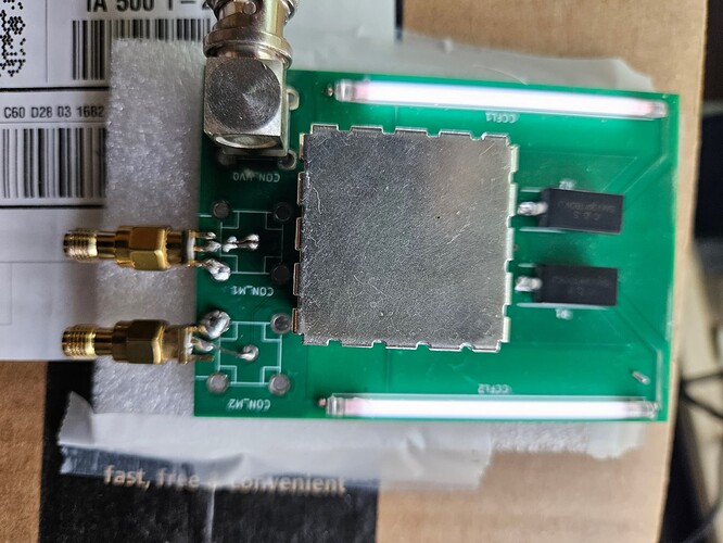
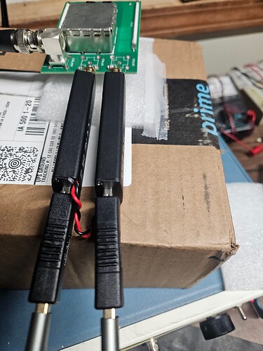
* These are the two antennas – plasma antenna CCFLs mounted on a PCB. In this photo they are hooked up to my failed effort to contain the expense of this project by wiring the clock of one RTL-SDR V3 to the other’s – which unfortunately did not provide adequate coherence for the phase detection as well as requiring a good deal of work to configure the Kraken DOA software system correctly.

** Although the original experiment used the 19kHz FM pilot wave indicating stereo availability, in order to detect a phase shift of on the order of 100ns in that wave, long sample periods and an expensive Picoscope was required. And, yes 100ns is long compared to the 100MHz frequency and, yes, such a phase shift is not predicted by known physics. That’s what we’re trying to nail down in a system cheap and simple enough to replicate that there can be little doubt that this is, in fact, the real phase shift.

Yep you will need a USB-A to USB-C data cable to connect between the Kraken and Pi. And a 5V/2.4A supply for the KrakenSDR, and a similar supply for the Raspberry Pi.

Please check out 01. Additional Hardware Required · krakenrf/krakensdr_docs Wiki · GitHub for more information.

One note about coax cables: If you’re using coax to connect to the antennas, please make sure that the coax cables are the same length, and type. It’s possible that mass manufactured cables will have a rather larger length tolerance of 1cm or more.

If you’re only working at 100 MHz, this sort of tolerance is acceptable, but if you go up into the upper UHF you’ll definitely want tighter tolerance cables, or even specifically phase matched cables.

I’ve now got a KrakenSDR DOA system up and running with the standard hardware and software configuration.

What I would like to do now is disable all but 2 of the antenna ports so that the DOA algorithms are operating in a degraded mode paying attention to only the 2 plasma antennas.

If one opens up the box and sets the 3 DIP switches to off, what must be done in the web interface other than changing it to be ULA?

Bear in mind that what I’m after here isn’t DOA but rather just a simple user interface – like the DOA curve provided by the web interface – that would permit one to by inspection determine whether there has been a qualitative change in the phase relationship between the two signals.

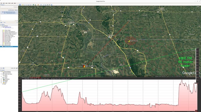
The actual experiment will require that the investigator travel to a very specific radius from an FM broadcast tower (yes I know – better not be too close to a powerful signal) where the theory expects that the plasma antennas will be 180 degrees out of phase compared to when the plasma is turned off.

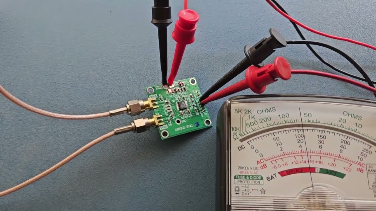
Hello. The simplest and cheapest way to measure the phases of two antennas is to use the AD8302 module ( LF–2.7 GHz RF/IF Gain and Phase Detector - AD8302). To work with this module, 5 volts is enough and the result can be observed on a simple multimeter or for this you can use a microcontroller with an ADC with a graphic display. Of course, you will need a very simple program for the microcontroller. Watch my video where I measure the phases of the emitters of a collinear antenna. Watch the experiment at 9 min 20 sec. https://youtu.be/CpfmLMtHfmE

UPDATE:

I went back to try the AD8302 again because I suspected the reason for my prior failure was due, in part, to the power supply I was using: 2 x CR2032 batteries in series rather than an ordinary 5V plug-in power adapter. I was able to get a reasonable read-out voltage for the 0 degrees phase difference with the 5V plugin supply. I had wanted an integrated power source for the AD8302, which is why I went with the battery supply.

However, this still does not give the highly selective tuner/band-pass – which was a main reason for going the SDR route.

END UPDATE

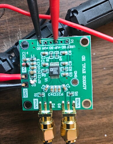
About a month ago I bought a couple of them and tried one out:

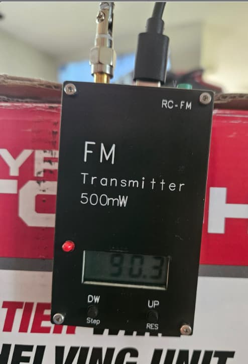
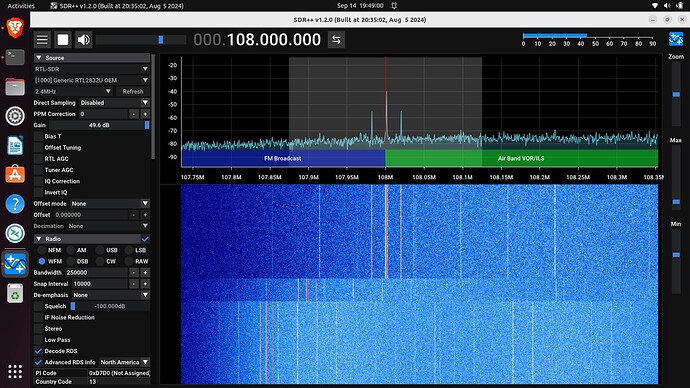
With this configuration I can’t get this AD8302 board’s phase/VP+ to register anything but 0.35V. Same for magnitude/VM+. The SMA’s are delivering signal and I even tried it with 30dB gain amplifiers. Tx: 0.5W 91MHz and 10mW 2.4GHz in close proximity in various positions so one would expect at least the magnitude/VM+ voltage to change. The scope clearly shows magnitude change with different positions of the 91MHz Tx.

The plasma antennas are mounted on a PCB:

The principal investigator (Steffen Kuhn) indicated that the antenna PCB needs to include a resonant circuit to select the FM station’s frequency and low noise amplifier to push the signal off the PCB to the AD8302. This would, in turn, require trimming capacitors.

In his opinion this is so tricky that in his experiment he resorted to using standard FM radio tuners which, because the carrier is demodulated out of the signal, outputs only audio frequencies. He filters that to extract the 19kHz pilot (the presence of which indicates stereo FM). He then runs that into a 100MHz PicoScope to digitize at 5MHz and then further interpolates to reconstruct the 19kHz with adequate phase resolution to detect the 100ns phase shift that he expected at his distance (23km) from the FM broadcast tower.