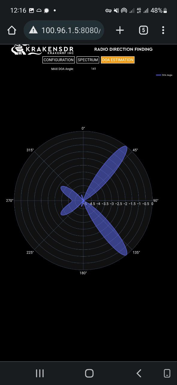
Hello. I am trying to set antennas into Linear Array (ULA) in order to improve accuracy, but I can not quite comprehend how to read the DOA angles correctly. I have created this beautiful image, which shows the linear antenna and 4 measurement cases:
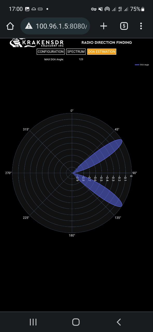
Test1 - the radio is 45 degrees relative to the array line
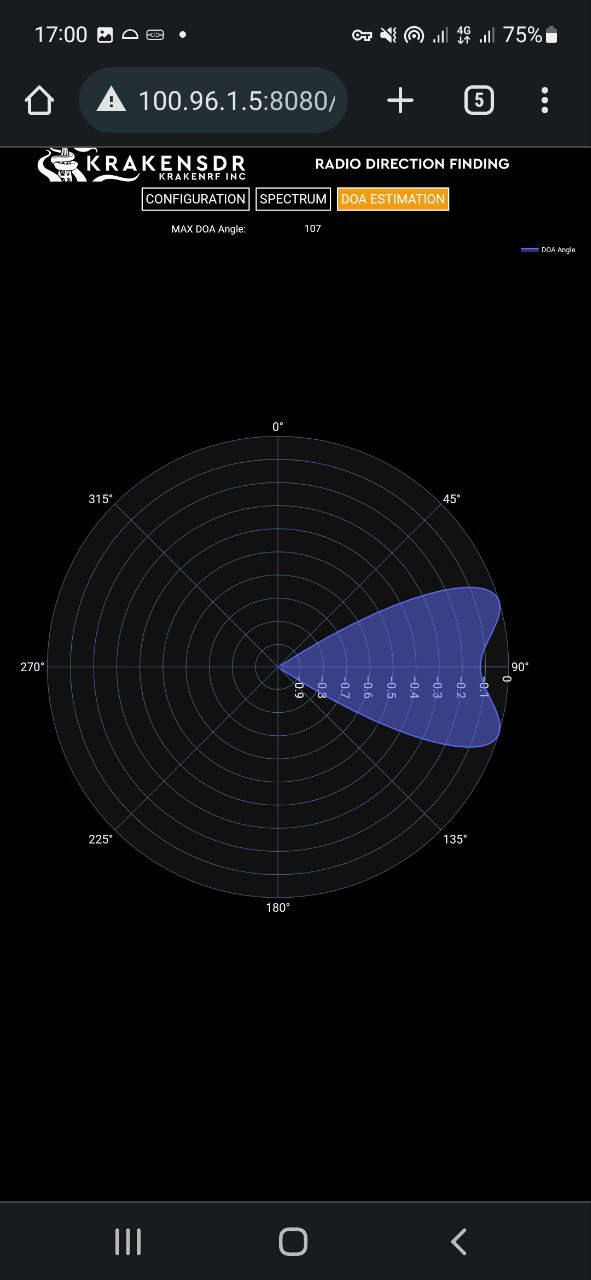
Test2 - 90 degrees
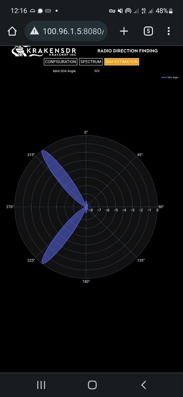
Test3 - 135 degrees
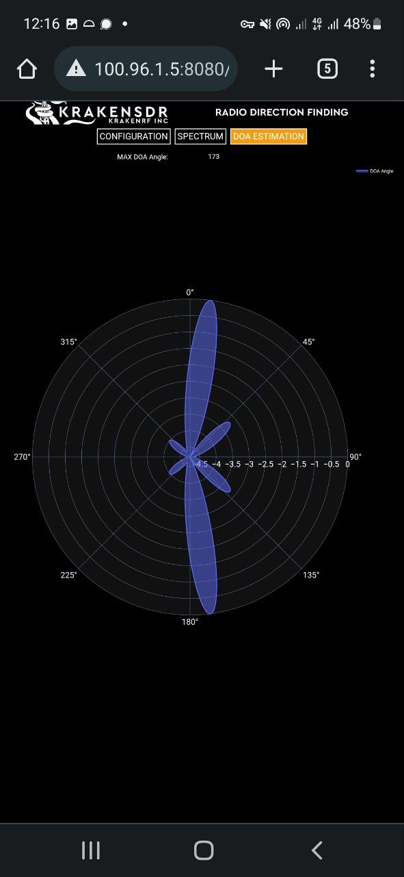
Test4 - 180 degrees (the radio is on the line with the array)
I have noticed that the signal is mirroring over the line 90*-270*, i.e. the Kraken is not sure where it is - at the front or behind the array (which is fine). But is line 90-270 the line of the array? I.e. is 90* DOA mean that the radio at the left from the antenna array, 180* - at the front (or behind), and 270* - at the right?
I believe the probability of output being 45* vs 135* is the same, right? Also, are there any corner cases with the DOA output that may need knowing? Thank you
Yes the two solutions are equally valid. If you have some prior knowledge about the signal direction, you might be able to rule one out.
Alternatively, if are driving around you’ll find that the true angle will converge, whilst the false angle will diverge. So in time you will get the solution.
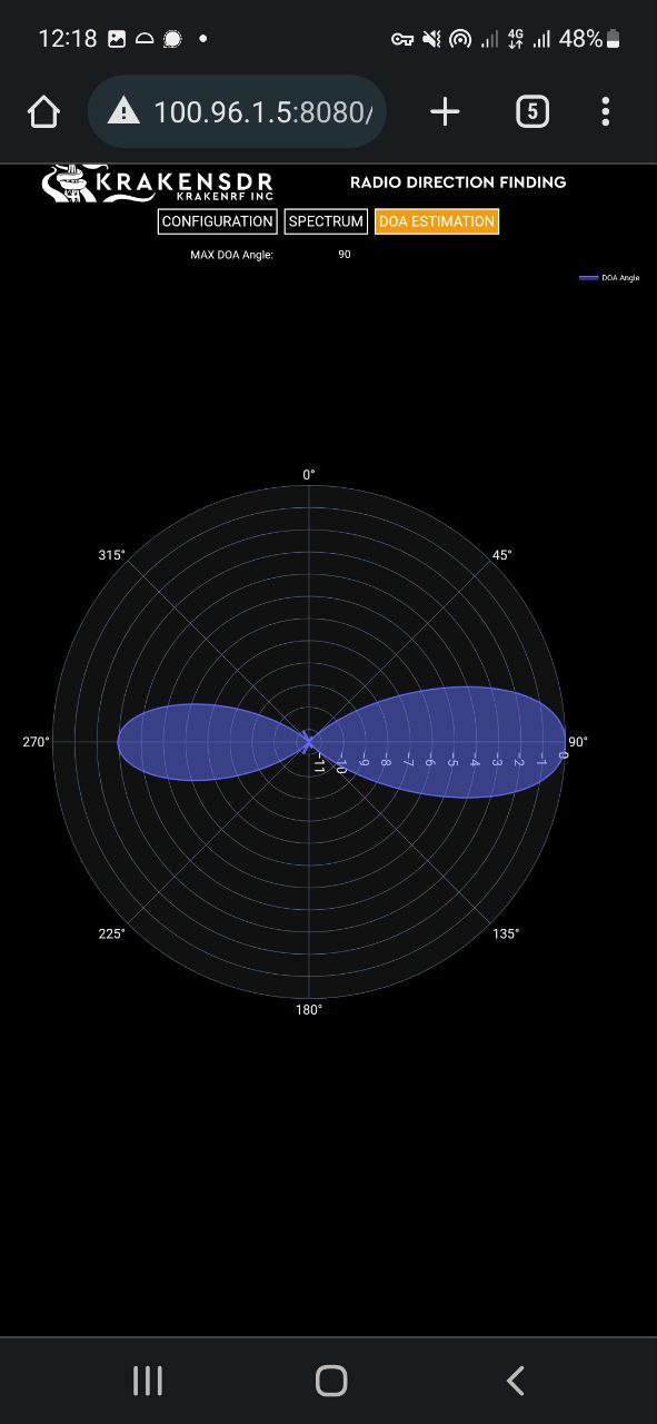
But ULA on a car could be slower to converge compared to UCA. Since there is only a limited range of usable angles. You’ll see that for signals coming from the +90 / -90 ends of the array (like in Test 4) you’ll get very poor results, so only mostly orthogonal signals will work well.
This is because the array looks very tiny from the sides so you loose aperture. With the worst case being that the array looks like a single element from the +90 / - 90 degree angles.
If I enable Forward/Backward (FB) averaging and have an idea about the anticipated position of a signal (either forward or backward of the ULA antennas), would enabling this feature restrict the output to only the expected position (e.g., 45 degrees) or include the mirror angle (135 degrees) as well, as in the case when it is not enabled?
That’s the idea behind the “ULA Output Direction” setting. If you have prior knowledge about the direction, you can truncate the mirror angle, so it doesn’t show up in the output.
Hello, do you know what is the minimum signal duration that Kraken sdr can detect? For example, can it detect burst signals with duration some micro seconds?
If you are squelching on weak, very narrowband CW signal bursts that have pulse periods less than about 50ms this option will help detect them better at the expensive of some computational power.
Bursts below 50 ms are possible, but we don’t know what the absolute minimum traceable is.
Thank you. I want to detect a signal that has bandwidth enough greater than 2MS which is the maximum rate of kraken SDR. Specifically, my signal is about 20MHz, I don’t want to reconstruct it (get information from that) I just want to detect the DoA of some repeated burst pulses of duration 0.2 usec with repeat interval 526 usec. According, Shannon & Nyquist I need at least 2 * (1 / 0.2e-6) = 10 MS bandwidth in order to have the duration of 0.2 sec to correspond to an integer number of samples.
PS: I don’t know if I can do something with sub-Nyquist rate.
If it’s radar there will be several pulses within the integration period. Assuming they’re all from the same source, then it will still work. The bandwidth doesn’t matter, even if the radar is wideband you can take a sub section of that bandwidth and it will still be sufficient.
A radar can have pulse duration from 0.07 usec to 0.5 usec and based on rpm and PRF the interval between this pulses can be around 500 usec. What do you mean integration period? Is it related to the DoA algorithms? If yes, what is a typical value?
If the previous statements are correct then there is the possibility to detect a signal using DoA without seeing it in spectrum (i.e in max hold). Correct?
Reducing the block size will reducing your processing gain. You can play around with the block size using the DAQ settings in the GUI (they’re hidden behind a checkbox), but I would recommend leaving it as default unless you really need to change it.
You don’t need to exactly match the transmission period to the block size. It’s okay if some parts of it are empty.