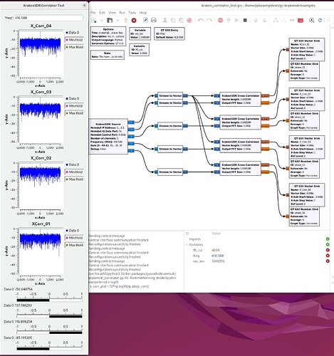
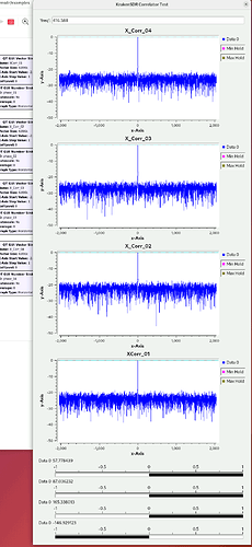
Below is a screenshot of the kraken_correlator_test provided by gr-krakensdr.
A few questions about this output (the graphical window to the left of the gnuradio graph):
-
At the bottom are black and white bars from -1 to 1 that seem to indicate the sign of the phase given in degrees just above in the line that reads:
Data 0 <degrees>
Is this bar meant to simply be a visual indicator of whether the signal is leading (-) or lagging (+) channel 0?
-
If the number is degrees phase, shouldn’t the number be close to 0 degrees if that antenna is adjacent to the antenna for channel 0? In my case the antenna for channel 1 is within a couple of inches of channel 0’s antenna, yet I’m seeing a phase that varies between -90 and -50 degrees – usually midway (-70).
-
Not directly related to the output interpretation, but: Why the modification to rtl_daq.c to turn the shared internal noise source on continuously? (I may have a fundamental misunderstanding of the “phase” being measured here. I did notice a change in the behavior of this GR block when I have antennas hooked up vs not hooked up, so I presume the phase is whatever external RF signal is being detected at the frequency given by the GR graph’s variable called freq (see #2 above for my lack of confidence here).)
-
In my use case, I simply want to measure the phase difference between channels 0 and 1 at 103.1MHz. Can I:
4.1) Set the freq variable to 103.1,
4.2) feed the histogram and file sink GR blocks the phase output of “KrakenSDR Cross Correlator” block to collect samples of the phase difference, and
4.3) in “KrakenSDR Source” reduce the “Number of channels” to 2 without bothering to alter the configuration file at ~/krakensdr_doa/heimdall_daq_fw/Firmware/daq_chain_config.ini?
Questions about this screenshot with the noise source continuously on:
- Regarding “It’s not always perfectly 0”: The GUI Numbers Sink section at the bottom shows angles all of which are quite far from 0 degrees. Unfortunately, in the documentation’s screenshot, we are not shown what these numbers should be because that screenshot cuts off all of that section. So the question is: What is the meaning of those angles?
- “The idea behind the correlator_test flowgraph is that it is a test to check that the KrakenSDR is phase coherent.” What effect should disconnecting an antenna have during the test with the noise on continuously? I noticed that there is a big difference between having the antenna connected and not having an antenna connected. I thought the test with noise on did not measure phase of the antenna signal. “If you turn it off you are then measuring the ambient RF.” If so, then, here again, “What is the meaning of those angles?” with the noise source on continuously?
- “First you do need to adjust the configuration file to run the number of channels you are using. Then make sure the noise source is off for your test. Then it should be OK.” This sounds like you’re saying that it may be important to turn off the other channels (ie: all those other than 0 and 1) during my attempt to detect the phase difference between 0 and 1. But that doesn’t make sense since the other channels are all passive receivers and therefore should not affect the incoming signal (let alone the spacing between the antennas for 0 and 1). I originally mentioned possibly needing to take apart the KrakenSDR box to get at the dip switches only because it appeared to me that some sort of unexpected interaction between the channels was causing my difficulty in getting a stable phase relationship. Could I simply leave not just the DIP switches unaltered but go with the default configuration and look only at channels 0 and 1 in gnuradio?
Those angles are the phase of each tuner. I’m not sure why you are seeing such high phases on yours, they should be all close to 0 if you have the noise source turned on always. Are you sure that you did the code change to force the noise source to be always on and recompiled it after?
If the noise source isn’t on then that should be showing you the compensated phase difference of each input relative to the reference input.
You can check the code producing that angle measurement here gr-krakensdr/python/krakensdr/krakensdr_correlator.py at main · krakenrf/gr-krakensdr · GitHub
phase = np.rad2deg(np.angle(x_corr[N]))
You don’t have to disable the other tuners if you don’t want to, you can choose to simply ignore them.
I got it to work. With the noise source on the phase difference between channels 0 and 1 was less than a degree from 0. However, with the noise source off I’m seeing small, but still substantial, phase difference of between 6 to 9 degrees. I’ll be continuing work to see if I can figure the source of this error.
I’m now attempting to come up with a script to run on a fresh SSD burn of the Raspberry Pi 4 image on my RBP4 system and make only these changes before connecting via Gigabit ethernet to deliver samples via ports 5000 and 5001. To do so, I configure my Ubuntu laptop’s ethernet port to share its wireless Internet connection so that the RBP4 acquires an IP4 address that ssh from the laptop to the RBP4 can tunnel ports 5000 and 5001 to localhost. With that in place I can log into the RBP4 and make the mods to the RBP4:
- out_data_iface_type = eth
in
heimdall_daq_fw/Firmware/daq_chain_config.ini
-
                //rtlsdr_set_bias_tee_gpio(rtl_rec->dev, 0, 0);
             rtlsdr_set_bias_tee_gpio(rtl_rec->dev, 0, 1);
in
heimdall_daq_fw/Firmware/_daq_core/rtl_daq.c
3) make (within heimdall_daq_fw/Firmware/_daq_core)
4) cd /boot
5) sudo mv start_kraken.sh start_kraken.sh_stop
At this point, the RBP4 image can be saved off for others to use download as a phase difference detector to reduce the complexity of setting up the KrakenSDR as a phase detection system via kraken_correlator_test,
I suppose an additional two steps might be appropriate as a replacement for the /boot/start_kraken.sh script so that it boots up with ports 5000 and 5001 active:
- cd ~/krakensdr_doa
- ./heimdall_only_start.sh

