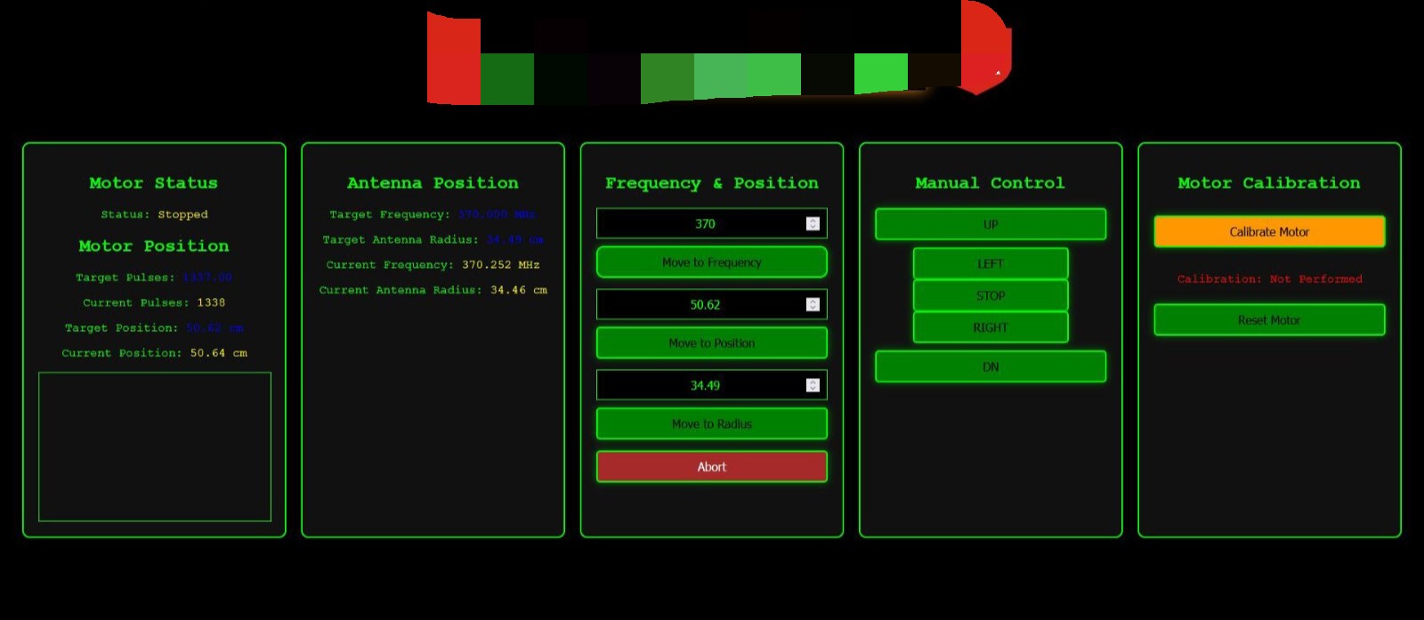
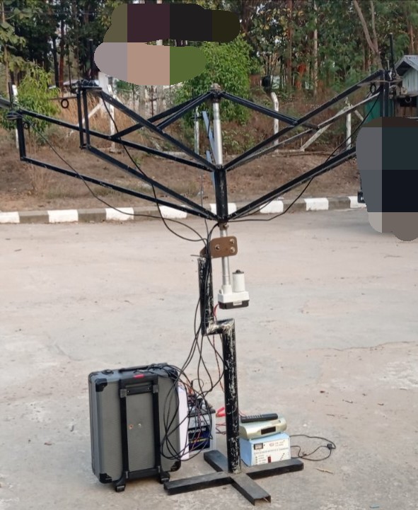
We made Krakenrf’s Antenna Array moveable by remote control. We wrote a program to move it according to the frequency and width. We also wrote the motor control using the Raspberry Pi as a web version.
Is my action correct? Please give me some advice.
1 Like
WOW! Silly me, I just use a measuring tape. Is this just a “will it work” project, or do you have plans to market it?
The project I am working on is trying to control a Direction Finding System remotely. I am skeptical about KrakenSDR being able to calculate the correct direction for all VHF / UHF frequencies. Even when there is no interference, and when testing in a good Line Of Sight location, it still shows direction errors. I tested 138Mhz, 146 MHz, 152 MHz, 160 MHz, 173 MHz and UHF from 350 MHz to 480 MHz. Only 3 were accurate, the rest were wrong. KrakenSDR challenged me with a table that changes the antenna width according to the frequency. Now, when I put the antenna array according to that table and test it, I see that the result is not good. Finding the DF of high-power FM transmitters is no different from finding the DF of handheld radios. Can KrakenSDR provide a better solution? I would like to know what can be improved and what needs to be done to be more accurate.
The antennas you use / the height of the antennas, is just as important as the spacing. For more accurate RF you should consider which antenna is best for your frequency range. It is not possible to have the same antenna for VHF and UHF, without seeing issues. For most using a 1/4 wavelength antenna is standard. For example a 138MHz 1/4 antenna ~542.5mm, whereas a a 480MHz 1/4 wavelength antenna ~156.25 mm. Big difference. You should also check if the antenna has got any specific bandwidth tuning, you can also look at using bandpass filters to also further improve accuracy for a specific frequency range.
Is antenna length (tuned) really an issue with a receive system? I understand that a 'tuned" antenna will xmit better, and possibly receive a slightly stronger signal, but is it critical for Direction Finding uses?
Even though the antennas are physically identical within a given setup, they still need to be electrically appropriate for the frequency you’re working with. A ¼-wave antenna tuned for 150 MHz will not behave the same way at 138 MHz or 480 MHz. While it may still receive signals, its radiation pattern, impedance, and phase response will be off, especially outside its design band. Since KrakenSDR relies on very small phase differences across antennas to determine direction, even minor inconsistencies introduced by frequency mismatch can skew the results.
So yes — for accurate RDF, you do need different (but matched) antennas for different frequency bands. For example:
- A ¼-wave VHF set for 150 MHz (~500 mm length) will work well from ~138–173 MHz, with some compromise.
- For UHF (350–480 MHz), you’d need a separate set of shorter antennas (~156–214 mm range) tuned to that band.
Swapping antenna sets to match the frequency band you’re scanning is the best way to maintain DF accuracy. Using a “one-size-fits-all” antenna across widely spaced bands will reduce performance due to changes in pattern and phase behaviour — even if all antennas are technically the same.
2 Likes
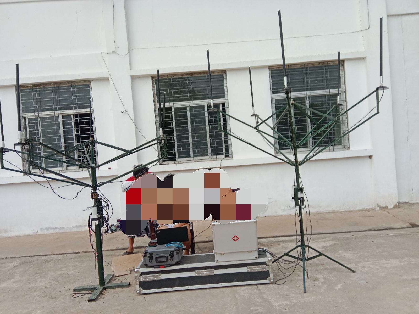
Firstly, that is a really cool array!
For performance some things to consider:
- Do those antennas require a ground plane to operate correctly?
- Are you confident that your cables are all of identical lengths, and identical builds? Even a few cm difference can throw things off.
- The cables are quite messy. It is advisable to keep all the cables running together in a sheath, or at least cable tied together. This makes it so that any bends in the cables (which can affect phase) happen to all the cables identically.
- When testing make sure that you are in the far-field of the antenna. For lower frequencies that can be a few meters away. If you test within the near field, results will be poor.
- Also when testing, if you are only within a few meters of the array, you will want the transmitter to be at the same height as the elements. Testing below the radiation pattern horizon could cause odd results. This becomes less of an issue the further away the transmitter is.
- Any walls or obstructions near the array can throw off results by causing multipath reflections.
- I assume that you are remebering to correcting adjust the antenna spacing parameter in the Kraken web UI too, whenever you make an array radius change?
- What transmitter antenna are you using? The transmitter antenna should also have a good radiation pattern for the frequency being used (this is safe to assume for commercial transmitters, but if you’re using a random whip on your test transmitter it may not be the case). If the radiation pattern is wacky, multipath will be more prevelant, as reflections could be seen as stronger than the signal going out to the horizon.
- Finally, those antennas will need to have decent SWR on the bands you are working with. You may also wish to measure their phase responses with a VNA and see the frequencies at which there is a discontinuity. Where there is a discontinuity, there will be poor performance in that region, especially if the antennas are not exactly identical in terms of manufacturing precision.
1 Like