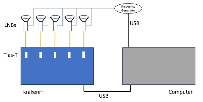
I would like to use krakenrf to determine the direction to the transmitter even at frequencies above 1.7ghz. I have thought of a setup for this. The idea is to connect a modified LNB to each of the five inputs. I would desolder the 20MHz quartz on all LNBs and replace it with a common frequency generator. Has anyone done this before?
Yes if all the LNBs are run from the same clock, it should be possible to do this.
We have tested a downconverter prototype that works in a similar way to what you show (without the LNBs though) and it works.
Is there a limit in time resolution so the wavelength becomes too short for detecting the phase difference?
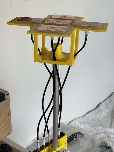
I have an idea of using 5 patch antennas in array at 1700 MHz and using 3D beam forming to track satellites (without ![]() ). Are there some limitation that I should be aware of?
). Are there some limitation that I should be aware of?
No limitations like that. The main concern at those frequencies is to ensure your array is precisely spaced and that any filters or LNAs in the antennas aren’t causing phase shifts. Also make sure that your cables are exactly the same length, and probably at those frequencies you also need them phase matched too.
Another question, as i can 3D print the patch elements, they are put in place with 0.1 mm accuracy.
What configuration would you recommend to scan for elevation and azimuth with 5 antennas:
a) elements in a cross
-0-
000
-0-
b) elements in corner
0-0
-0-
0-0
c) circle like for dipole in kraken excel sheet
 -00
 0--0
  -0
The code doesn’t currently support az/el simultaneously, so you’d need to do some modifications for that.
I also don’t know exactly what arrangement would be best. Every arrangement with only 5 elements is kind of a compromise. Assuming you are using the patch antennas in a linear format, probably cross or corner would work well.
Really interested to buy KrakenSDR. Just waiting for ability to go above 1700MHz. Any news for mentioned converter?
has anyone tried pushing kraken to higher frequencies without any hardware modifications? maybe there is a way to overclock the driver or some other trick?
The driver already allows you to tune beyond 1.766 GHz using some harmonic tricks, but the result is always poor. I believe the method of getting those higher frequencies results in poor phase measurement performance which is critical.
Wideband kraken is still in the works.

