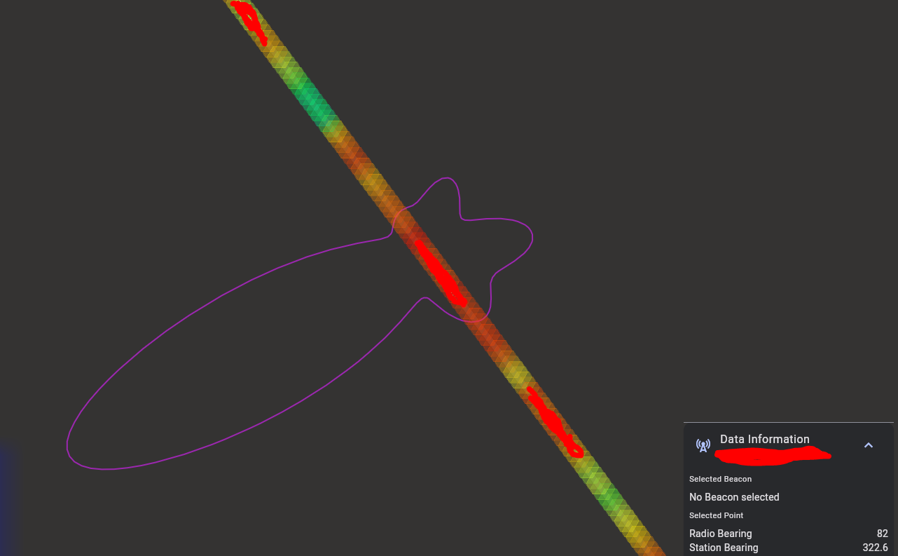
I’m post-processing data from testing that I have done to evaluate the capabilities of the Kraken at higher frequencies greater than 1GHz. Loading the .csv logs in the Cloud Mapper I get the following image (similar image for most entries in the .csv file). There is a nice “tight” lobe which in indicates that the transmitter should be to the Southwest while in reality the transmitter is to the Northeast.
What antenna array and array dimensions did you use? Remember that the Krakentenna set is not made for frequencies over 1 GHz. For over 1 GHz a custom array will be required.
The lobes could also simply be offset from multipath. Are they all pointing in the same direction?
Array size is 8cm. I’m not using the Kraken antenna set but using appropriate antennas mounted on a a ground plane for the frequencies of interest (up to 1600 MHz).
I’m thinking that It could be multipath/interference. There are a few other antenna mounted on my vehicle but steps were taken to make sure the Kraken array’s phase center was higher than the other antennas but they still could be having an effect on the Kraken
Just to make sure I am understanding Max DoA correct, this is the bearing estimate for the current processing interval? The heatmap tool does not end up using the Max DoA in it calculations?
When plotting the 360 degrees of DoA values, are these in unit circle convection referenced to the current heading or 0 degrees (east)?
Max DOA is just the direction of the peak of the current lobe.
The max value is not specifically used in the heatmap calculation apart from it being a part of the set of values that describe the lobe.
In the web GUI you can choose to plot Polar or Compass. Polar is in the unit circle convention and Compass is in the mapping convention.