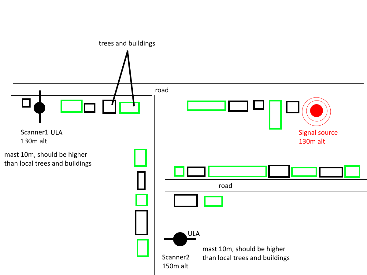
Hello. I’ve run some DOA accuracy tests with two scanners and custom antennas (ULA, 5 dipoles with lowest SWR at 424 MHz + LNAs) and noticed a DOA deviation that changes with the frequency. What I mean is that at frequency X the DOA would be Y, but at frequency X+10 the DOA would be slightly different, but stable - on each PTT press it shows the same result. The distance between both the two scanners and the radio source is around 1 km. This is a village area, so there is a certain amount of obstacles like trees and small houses, but each scanner antenna and signal source are on the top of the 10m mast.
As you can see, there is a certain correlation between the frequency and DOA angle (with the exceptions), i.e. DOA kind of shifts counter-clockwise when you lower the frequency and vice versa.
The same effect is much less noticeable at longer distances, up to 10 km, but still exists.
Most likely it is related to the natural obstacles like tall trees, but I was worried that I messed up with the phase-symmetry of antennas or cables (even though I checked them with my VNA), or maybe there is another reason for such behavior.
P.S. what is the acceptable deviation of cable length (or phase value) or dipole size at 400-500 MHz? I.e. what are the acceptable phase-symmetry requirements?
The LNA’s could introduce phase offsets that can cause the DOA angle to be skewed in one direction, and the phase offsets will be affected differently at different frequencies. Same with cables that have poor length precision.
But I think the issue is just more to do with the wavelength multiplier changing with different frequencies, and therefore the multipath induced skew changing.
With small arrays like ours (5 elements is considered small), multipath and refractive effects can more easily “pull” the measurement away from the true angle.
When you increase the frequency, and leave the array size fixed, you are altering the effective resolution of the array. So at higher frequencies you’ll have better resolution, and therefore multipath and the refractive effects will pull the signal around a bit less, which could explain the angle changing.
To get around this the only real way is multiple readings from different locations to average out the multipath effects, which is why the mobile system works so well. Multiple distributed sites can also help. Or you need to use something like a much larger 16 element array.
At 500 MHz you can maybe 1-1.5 cm of play in cable length precision before you start getting poor results.
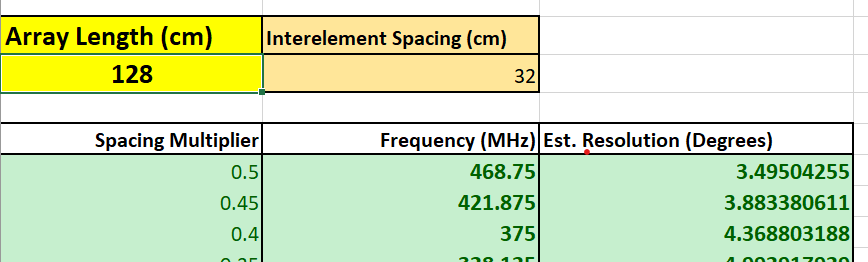
Basically, the resolution delta for 420 and 460 MHz is less than 0.5 degrees, and the spacing multiplier varies from ~0.45 to ~0.49. Can it still cause such a deviation? I just want to make sure this is not an LNA or cables problem
Regarding the LNAs:
I’ll try checking the DOA deviating with and w/o LNAs to make sure amplifiers are not the reason for the problem
Can I measure the phase shift of the amplifiers using a VNA? I assume if powered simultaneously by Kraken Bias T, the phase shift of all 5 LNAs has to be identical for the system to work correctly, right?
Could you please recommend an LNA that works properly with the KrakenSDR (in terms of the phase shift too)? Maybe you have already tested some models. I like the overall system sensitivity that LNAs introduce and would like to stick to them
I suppose it could still cause a deviation like that. But these errors are all a combination of everything in the chain, so still wise to check if yours cables and LNAs are causing issues.
Yes a VNA should be capable of measuring the phase shift. Export the plots and compare with each LNA.
I don’t have a recommendation for an LNA unfortunately. I tested with standard SPF5189Z LNAs, and there was a deviation of around 3 deg.
Greetings All,
I’m brand new to the KrakenSDR Forum & the KrakenSDR, but I’d like to chime in on this topic, After reading the manual, I would expect that bearing changes due to frequency change while keeping the array dimensions constant would be the main source of bearing “error” for a fixed antenna array. However, that being said, I would think that, unless the 0 antenna “heading” would have to be precisely aligned to the zero heading, and the other four antennas would also have to be precisely positioned on their respective azimuthal angles , as well as their relative spacing along the arc/circle of the array for each frequency, additional errors would creap in as the array was adjusted for different frequencies. Also, owing to the monopole characteristics, beam lobes will change as frequency is shifted for a given extension of the antennas themselves.
On the topic of phase change introduced by the LNA on each antenna, you might inquire with minicircuits technical support as to their device-to device variation
. You may even be able to request they match phase delay to some specification if their batch production specification is outside your need for bearing precision. However, there will likely be some charge associated with your request. Best to talk directly with minicircuits.
Please feel free to correct me where I may have gone astray.